An Engineering Drawing Shows The
An Engineering Drawing Shows The - A common use is to specify the geometry necessary for the construction of a component and is called a detail drawing. Show how a product can be assembled and how the separate parts fit together, with dotted lines showing where the parts slide into place. Web just as an architectural drawing or blueprint shows you how to construct a building, an engineering drawing shows you how to manufacture a specific item or product. In those cases, we have very powerful tools available to us. In this guide you’ll learn: 1.4 types of engineering drawing:
Types Of Dimensions In Engineering Drawing at GetDrawings Free download
According to iso 29845:2011, drawing is “technical information, given on an information carrier, graphically presented in accordance with agreed rules and usually to scale.” In graphics communication practice there is the whole collection of different lines, which are used for drawing purposes. Engineering drawings use standardised language and symbols. Show how a product can be assembled and how the separate parts fit together, with dotted lines showing where the parts slide into place. Web in introduction to engineering drawings, we showed you the building blocks of engineering drawing.
Web In This Way, An Engineering Drawing Can Actually Show More Information Than A Photograph Taken In The Same Orientation.
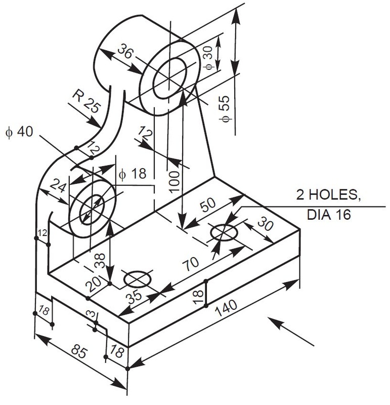
Web the engineering drawing rules are defined and embodied in the publications of standards organizations (for example, iso and asme ). Web structural drawings are a series of pages which explain and illustrate the structural design intent of a building or structure. One can pack a great deal of information into an isometric drawing. Web how to read engineering drawings.
The Diagrams Also Show Components That.
1.3 importance in various fields like mechanical engineering, civil engineering, etc. Web an engineering drawing is a type of technical drawing that is used to convey information about an object. The symbols used for each hole and how they are shown on engineering drawings. Basically, this type of drawing aims at clearly capturing all the geometric features of products and.
What Is The Main Image, Which We Are Using In All Our Projects, Designs, Drawings?
A complete understanding of the object should be possible from the drawing. Web an engineering drawing is a subcategory of technical drawings. Web engineering drawings, also known as mechanical drawings, manufacturing blueprints, drawings, etc., are technical drawings that show the shape, structure, dimensions, tolerances, accuracy, and other requirements of a part in the form of a plan. It is more than simply a drawing, it is a graphical language that communicates ideas and information.
Web An Assembly Or Subassembly Drawing Showing All The Standard And Nonstandard Parts In A Single Drawing.
This is a complete guide to the types of holes found in machining. Tools and equipment for engineering drawing. This makes understanding the drawings simple with little to no personal interpretation possibilities. Web 1.1 definition and overview of engineering drawing.
What is the main image, which we are using in all our projects, designs, drawings? Web an engineering drawing (also named as mechanical drawing, manufacturing blueprints, drawings, dimensional prints, and more) refers to one of the technical drawings, which helps to define engineering products’ requirements. If the isometric drawing can show all details and all dimensions on one drawing, it is ideal. A complete understanding of the object should be possible from the drawing. The aim of a good set of structural drawings is to provide the reader with enough information to:


